Votre panier est vide !


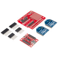
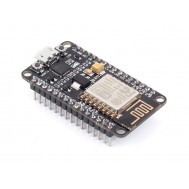

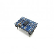


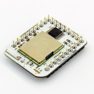
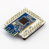
Microduino BM
Prix :
2.500,00DA
H.T : 2.500,00DA
| Modèle : | DZD000422 |
| Disponibilité : | 4 Ã 8 Semaines |
| N° de visites: | 1097 |

Microduino-BM is a discharge module which combines a single-cell Li-ion battery charge management, power detection and LED indication. The output voltage is 5V, and LDO is 3.3V output. Provides the outstanding battery management for the Microduino-Core module.
Microduino-BM
- Microduino Li-ion battery management module
- full functions of charge, discharge, voltage dectect and LED indicator
- DC-DC convert, support 3.7->5.V and 3.7V->3.3V.
- UPin-27: Microduino standard interface
- Integrated functions that charge/discharge management, power detection, 5v output, 3.3v LDO;
- Toggle switch controls the charging and discharging, reboot and sleep mode;
- Small, cheap, stackable, opened platform;
- Define unified interface Microduino specification and contain rich peripheral modules. Set up the quick connection with other Microduino modules and sensors easily and flexibly.
- 2.54 pitch row female connector for easy integration into breadboard.
Interfaces
- A pushbutton switch
- A two toggle switchs
- One pair of 2.54 battery interface ("+" for positive, "-" for negative)
- UPIN27 contains the 5V, 3V3, GND interface:
Charging
- First connect the external 5V power, and then set the pushbutton switch to "IN" position, the module goes into the charging state, then four LED lights flash to indicate charging (detailed display mode, please refer to HT4901 document), the maximum charging current is 500mA. Finished charging,turn the pushbutton switch to "OUT", and unplug the external 5V charging power.
- Note:
- Always follow the charging process: make sure switch to "OUT", plug in the battery, connect external 5V power, switch to "IN", start charging, After charging completed, switch back to "OUT" , unplug the external 5V Charge power.
- Recommended charging power supply: Voltage 5V, current 600ma above;
- Don't add voltage-drop elements (such as diodes) in the charging circuit. These will reduce the charging current because of lower charging voltage.
Discharge
- Make sure the switch is in the "OUT" firstly. After connect to the battery, the module is in the standby mode, then short press button switch (timer> 50mS), the module will be wake up from standby mode. Voltage output will start at this time, and open UPIN27's GND circuit: Interface 5V outputs 5V voltage, maximum current is 500mA; while 3.3V interface outputs 3.3V voltage, maximum current is 250mA.
- When the battery voltage under-voltage (3.3V) or enter limiting / boost output short circuit protection, enter standby mode.
- Note:
- sure the switch is in the "OUT" and then start the boost output;
- please do not toggle the switch in Battery-powered process.
Power detection
- Make sure the switch is in the "OUT", after access to the battery, press button switch on the built-in battery detection. The four LEDs use to battery indicator, and last 3 ~ 5S.
Standby
- Standby means that disconnect the circuit UPIN27's GND circuit. In this state, BM can be controlled within the overall power consumption of 30uA.
- Make sure the switch is in the "OUT", if no any action after accessing the battery, then the default mode is in standby mode.
- If you've turned on discharge mode,, pressing the button switch (3s above) to re-enter into standby mode.
- Intelligent Detection: No charge input, no discharge output (<10mA) within three minutes will enter into standby mode.


Écrire un avis
Votre nom :Votre avis : Note : Le HTML n’est pas pris en charge !
Évaluation : Mauvais Bon
Saisir le code ci-dessous :
Service client
horaire d'ouverture
Nous contacter
- +213 540 265 592
- +213 45 366 373
- +213 540 265 592
- contact@dzduino.com
- Cité 122 Logements, Bloc A3, N°14 Chemouma - Mostaganem (En Construction‬â€)
Dzduino Retail Store


Dzduino Electronics © 2013-2015. All Rights Reserved
Le produit est en rupture de stock. Entrez votre adresse email ci-dessous et nous vous informerons des que le produit sera disponible.
