Votre panier est vide !


Microduino Core+
Prix :
3.000,00DA
H.T : 3.000,00DA
| Modèle : | DZD000420 |
| Disponibilité : | 4 Ã 8 Semaines |
| N° de visites: | 1209 |

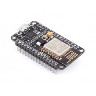
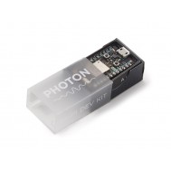
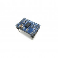
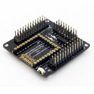
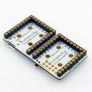
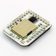
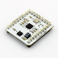
Microduino Core+
- Core board of Microduino series
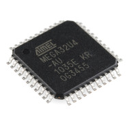
- Main chip: ATmega644PA/ATmega1284P
- As powerful as Arduino Mega2560
- 2 hardware serial ports, 10 more digital I/O
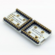
- UPin-27: Microduino standard interface
Microduino-Core+ is one of core modules of Microduino series, using Atmel ATmega644PA/ATmega1284P series as main chip, it is a performance enhanced version of Microduino-Core.
Microduino-Core+ has all features of –Core, can be stacked with modules through UPin-27 Microduino standard bus interface, as smart as Arduino Mega2560, but as small as a quarter. Moreover,Microduino-Core+ has 10 more digital I/O ports than Microduino-Core, provides 2 hardware serial ports, and more SRAM/Flash/EEPROM, it’s designed for high hardware resource required applications and designs.
Microduino uses the same development environment as Arduino IDE, designers can use the Arduino IDE, Processing on Microduino for idea realization, prototype development and low volume production. Programs can be smoothly migrated from Core to Core+ without any modification.
Microduino uses optiboot for bootloader, it takes less Flash than Arduino default engine and optimizes program uploading.
Currently, there are 4 different configurations forMicroduino-Core+ modules:
| Type | Flash | SRAM | EEPROM | Frequency | Supply |
| ATMEGA644PA @ 16M,5V | 64K | 4K | 2K | 16M | 5.0V |
| ATMEGA644PA @ 8M,3V3 | 64K | 4K | 2K | 8M | 3.3V |
| Atmega1284P @ 16M,5V | 128K | 16K | 4K | 16M | 5.0V |
| ATmega1284P @ 8M,3V3 | 128K | 16K | 4K | 8M | 3.3V |
Feature:
- Small, Stack, Strong
- Open source hardware, using the same development environment as Arduino IDE
- Microduino-Core+ can be burned with ISP, same as Arduino, easy "bootloader"
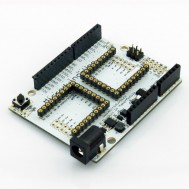
- Using the U-Shape 27-pin interface (UPin-27), the standard interface of Microduino, all Microduino modules and sensors can be easily stacked and extended through it
- Delivered ready to plug in.
- 2.54mm (0.1 inch) pin pitch, compitable to bread board and hole board
- Microcontroller: ATmega644PA/ATmega1284P
- Operating Voltage: 5V/3.3V
- Digital I/O Pins: 24 (of which 6 provide PWM output with D7,D8,D9,D10,D22 and D23, PWM ports are different to '''[[Microduino-Core]]''')
- Analog Input Pins: 8 (2 more comparing to Arduino Uno)
- DC Current per I/O Pin: 40 mA
- DC Current: 50 mA
- Serial: 2 set of serial ports. D0 (RX0) + D1 (TX0) and D2 (RX1) + D3 (TX1), used to receive (RX) and transmit (TX) TTL serial data.
- External Interrupts: 2, 3 and 6. These pins can be configured to trigger an interrupt on a low value, a rising or falling edge, or a change in value. See the attachInterrupt() function for details.
- PWM: 7, 8, 9, 10, 22 and 23. Provide 8-bit PWM output with the analogWrite() function.
- SPI: 10 (SS), 11 (MOSI), 12 (MISO), 13 (SCK). These pins support SPI communication using the SPI library.
- IIC: D20 (SDA) pin and D21 (SCL) pin. Support TWI communication using the Wire library.
- AREF. Reference voltage for the analog inputs. Used with analogReference().
- Currently, there are 4 different configurations for
| Type | Flash | SRAM | EEPROM | Frequecy | Supply |
| ATMEGA644PA @ 16M,5V | 64K | 4K | 2K | 16M | 5.0V |
| ATMEGA644PA @ 8M,3V3 | 64K | 4K | 2K | 8M | 3.3V |
| Atmega1284P @ 16M,5V | 128K | 16K | 4K | 16M | 5.0V |
| ATmega1284P @ 8M,3V3 | 128K | 16K | 4K | 8M | 3.3V |


Écrire un avis
Votre nom :Votre avis : Note : Le HTML n’est pas pris en charge !
Évaluation : Mauvais Bon
Saisir le code ci-dessous :

Service client
horaire d'ouverture
Nous contacter
- +213 540 265 592
- +213 45 366 373
- +213 540 265 592
- contact@dzduino.com
- Cité 122 Logements, Bloc A3, N°14 Chemouma - Mostaganem (En Construction‬â€)
Dzduino Retail Store


Dzduino Electronics © 2013-2015. All Rights Reserved
Le produit est en rupture de stock. Entrez votre adresse email ci-dessous et nous vous informerons des que le produit sera disponible.
